
IoT-Based ACMS Solution For Fire Fighting Monitoring
IgnisVigil connects critical fire-fighting infrastructure with real-time digital monitoring, helping users gain continuous visibility into pumps, pressure, water levels, equipment status, and system alerts.
Fire-Fighting Systems Need More Than Periodic Inspection
Fire-fighting infrastructure is critical to building and industrial safety, but conventional monitoring often relies on periodic physical inspections and manual checks.
Conditions can change between two inspection cycles, potentially leaving critical issues unnoticed. A pump may stop. Water levels may fall. Pressure may change. A valve may be left in an incorrect position. A control panel may lose power. A fault may occur in an electrical or communication circuit.
Without continuous visibility, important conditions may remain unnoticed between inspections.
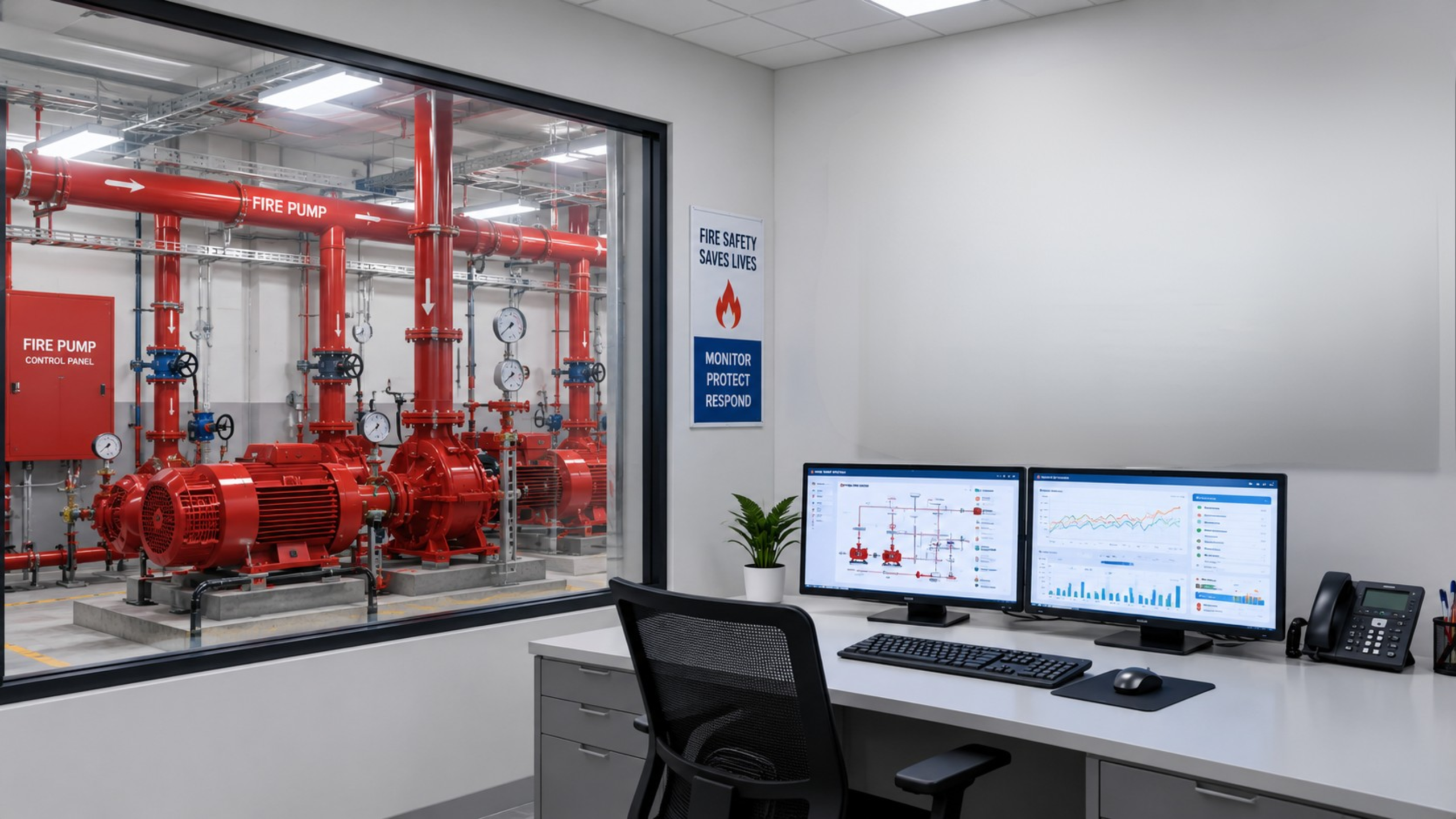
Manual Inspection
Regular physical checks can make continuous monitoring difficult.
Hidden Equipment Conditions
Critical changes in pump, pressure, water level, or power status may go unnoticed.
Delayed Awareness
System issues may only become visible after someone physically checks the equipment.
Scattered Information
Operational information may exist across equipment, panels, registers, and inspection records.
Introducing IgnisVigil
Connected Fire-Fighting. Continuous Visibility.
IgnisVigil is an IoT-based fire-fighting monitoring solution designed to connect critical fire-safety equipment with a centralized digital monitoring environment.
It collects operational data from connected fire-fighting systems, processes information through industrial IoT hardware, and presents system conditions through a centralized monitoring interface.
From Field Equipment to Digital Visibility
SENSE
Sensors and equipment signals capture critical fire-system parameters.
CONNECT
The Industrial IoT Gateway collects and transmits field data.
PROCESS
Connected information is organized for monitoring, alerts, analytics, and historical records.
MONITOR
Authorized users can view system conditions through a centralized monitoring interface.
ALERT
Configured conditions and threshold breaches can trigger notifications.
Critical Fire-System Parameters. One Connected View.
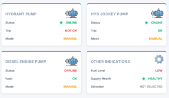
Pump Status
Monitor the operating status of connected fire pumps.
- Main Pump
- Hydrant Pump
- Sprinkler Pump
- Jockey Pump
- Diesel / Engine-Driven Pump
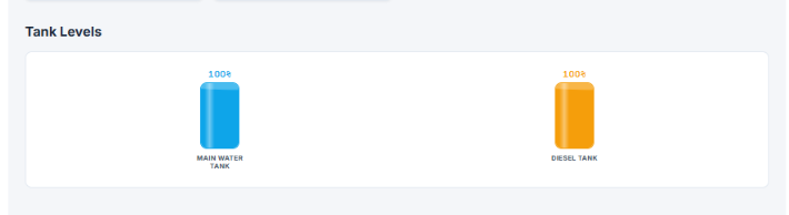
Tank Level
Track water availability in critical fire-water storage systems.
- Underground Tank
- Overhead / Terrace Tank
- Low-Level Condition
- High-Level / Overflow Condition

Pressure
Monitor pressure conditions across connected fire-fighting systems.
- Pressure Status
- Pressure Thresholds
- Abnormal Conditions
- Historical Trends
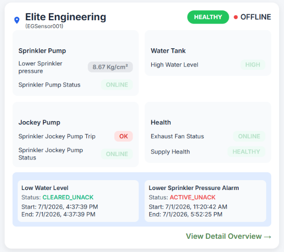
Fire Panel & System Status
Monitor connected control and fire-panel conditions.
- Panel Status
- Repeater Panel
- Power Availability
- Connected Equipment Status
See Your Fire-Fighting System. In Real Time.
IgnisVigil brings critical fire-fighting information into a centralized monitoring interface, allowing authorized users to understand system conditions without relying solely on physical inspection.
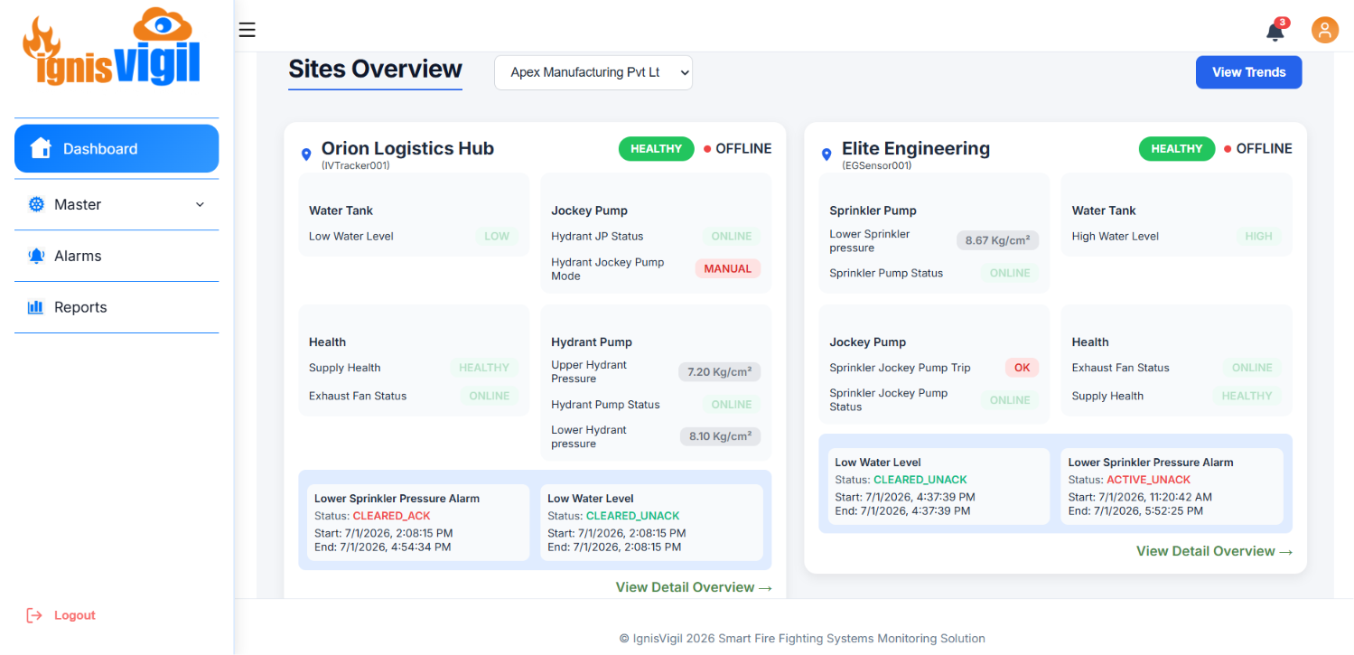
Know When Something Changes
Continuous monitoring becomes more useful when important system changes can generate timely notifications.
Pump Status Change
Receive notifications when monitored pump conditions change.
Low Water Level
Get notified when water levels reach configured limits.
Pressure Deviation
Identify pressure conditions outside defined thresholds.
Power Failure
Monitor loss of power to connected systems.
Equipment Fault
Receive alerts for configured abnormal conditions.
Built for Industrial Fire-Safety Infrastructure


Built to Connect With Existing Fire-Fighting Infrastructure
IgnisVigil uses industrial IoT hardware to collect data from connected fire-fighting equipment and transfer field information to the monitoring environment.
- Industrial IoT Gateway
- Digital Inputs
- Analog Inputs
- Equipment Feedback
- 4G / Ethernet / Wi-Fi Connectivity
- Local Data Logging
- Remote Configuration
From Periodic Inspection to Continuous Visibility
- Periodic physical checks
- Manual status checking
- Delayed issue identification
- Paper/manual records
- Limited historical visibility
- Equipment-by-equipment checking
- Continuous digital monitoring
- Centralized system visibility
- Configurable alerts
- Digital historical records
- Trends and event history
- Centralized monitoring
From Existing Fire System to Connected Monitoring
Site Assessment
Understand the existing fire-fighting infrastructure.
Parameter Identification
Identify pumps, tanks, pressure points, panels, and other parameters.
IoT Integration
Connect selected equipment and sensors with the IoT gateway.
Platform Configuration
Configure dashboard parameters, thresholds, users, and alerts.
Testing & Commissioning
Verify communication, monitoring, and alert behaviour.
Go Live
Start centralized monitoring of the connected fire-fighting system.